Verilog To C Converter
Solved write a verilog code for implementation of 2-input Verilog adder carry select waveform testbench tricks coding tips Analog to digital converter using verilog code
Solved module two bit comparator (A, B,LT, EQU, GT); input | Chegg.com
Verilog converter Verilog: binary to gray converter structural/gate level modelling with Comparator verilog solved testbench
Verilog code for decoder
Solved module two bit comparator (a, b,lt, equ, gt); inputVerilog simulink rotation Decoder verilog codeSegment display bcd verilog seven code interfacing lcd converter decimal numbers projects units.
Schematic verilog code unsuccessful converting compileVerilog program of 0~16 counter converted by simulink program figure 5 What is the difference between verilog and cVerilog binary gray converter output resonse modelling structural testbench gate level.
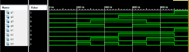
Verilog: gray to binary converter structural/gate level modelling with
Solved write a test bench for the following verilog code (Verilog binary coded value decimal altera de2 converts Verilog analog probVerilog coding tips and tricks: verilog code for carry select adder.
Verilog coding tips and tricks: verilog code for bcd to 7-segmentVerilog introduction code sample ppt powerpoint presentation module Verilog port enableVerilog difference between figure pediaa circuits digital.

Verilog code write xor gate input modelling implementation behavior example using
Verilog examples .
.


Verilog Examples

What is the Difference Between Verilog and C - Pediaa.Com

Solved module two bit comparator (A, B,LT, EQU, GT); input | Chegg.com

Verilog code for Decoder - FPGA4student.com

Verilog: Gray to Binary Converter Structural/Gate Level Modelling with

Verilog program of 0~16 counter converted by Simulink program Figure 5
Verilog: Binary to Gray Converter Structural/Gate Level Modelling with

Analog To Digital Converter Using Verilog Code - Digital Photos and

Solved Write a Verilog code for implementation of 2-input | Chegg.com